
Batteries are at the heart of the electrical systems found on any boat or vehicle. Proper battery management, including switching and charging, is essential for safe and reliable operation. The following basic wiring diagrams show how batteries, battery switches, and Automatic Charging Relays are wired together from a simple single battery / single engine configuration to a two engine, one generator, and four battery bank system. For more detailed wiring guidelines please consult a qualified marine electrician or one of the many books available on the subject.
Traditional Configuration

ON-OFF Battery Switch
Traditional Configuration

1 Selector Battery Switch
1 Automatic Charging Relay
Simple to Use

1 Dual Circuit Plus Battery Switch
1 Automatic Charging Relay
Most Flexible - Easily Isolates a failed battery

3 ON-OFF Battery Switches
1 Automatic Charging Relay
Simple System - House battery is shared with one engine. One engine battery is in reserve.

1 Dual Circuit Plus Battery Switch
1 ON-OFF Battery Switch
1 Automatic Charging Relay
Simple System - Engines share one battery. House batter is in reserve.

1 Dual Circuit Plus Battery Switch
1 ON-OFF Battery Switch
1 Automatic Charging Relay
Flexible

Can isolate a failed battery
3 ON-OFF Battery Switches
1 Automatic Charging Relay
Simple Operation - Can parallel batteries for extra starting power.
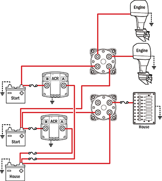
2 Dual Circuit Plus Battery Switches
2 Automatic Charging Relays
Can isolate any battery source from any batteries.

3 Selector Battery Switches
2 Automatic Charging Relays
---

3 Dual Circuit Plus Battery Switches
3 Automatic Charging Relays
Can isolate any battery source from any batteries.

4 Selector Battery Switches
3 Automatic Charging Relays