
DC ammeters require shunts for their operation. Some meters have built-in shunts, some meters have external shunts. External shunts are placed in the circuit where the current is to be measured. (See Technical Brief: Strategies for Monitoring DC Current) for a discussion about ammeter positions in DC electrical systems). Shunts and meters must be matched by their ratings and calibration. For example, a 50 Amp/50mV meter requires a 50 Amp shunt; a 200 Amp/50mV meter requires a 200 Amp shunt. (Blue Sea Systems’ meters read full scale deflection at 50mV).
How a Shunt Works. It is useful to think of water flow in a pipe when thinking about current flow in a wire. The way that a shunt works is analogous to a restriction to the flow of water in a pipe and a bypass around the restriction. Some of the water flow in the Main Pipe is diverted through the Bypass. A Paddle Wheel in the Bypass measures the water flow through the Bypass. If the Bypass allows 1/100th of the water in the main pipe to flow through it, and the Restriction allows the remaining 99/100ths of the water to flow through it, the ratio of flow in the Bypass to the Restriction is 1 to 99. Using this ratio, the Paddle Wheel could be calibrated to indicate the total flow through the Main Pipe.
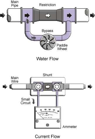 |
A DC ammeter and shunt works in a similar way—a small amount of current that flows through the Main Wire is diverted to, and measured by, the Meter. Analog meters have very fine internal wires that flex to enable the needle to move. Because the wires are fine, they carry only a very small current. Therefore, the current in the meter must be a tiny fraction of the total current to be measured.
In order to obtain an accurate reading of the current flow through the main wire, the shunt and meter are very precisely calibrated at fixed resistance values—the meter resistance is typically 50 Ohms and the shunt resistance is a fraction of an Ohm.
Example: 50 Ampere Meter. For a meter calibrated to 50 Amps full scale deflection, the meter will indicate that 50 Amps is flowing through the shunt when the meter reads 50 Amps. The shunt resistance is .001 Ohms. The ratio of shunt resistance to meter resistance is:
Therefore, when there is 50 Amps flowing through the shunt, there is 50 X 0.00002 = 1mA flowing through the meter.
Example: 200 Ampere Meter. For a meter calibrated to 200 Amps full scale deflection, the meter will indicate that 200 Amps is flowing through the shunt when the meter reads 200 Amps. The shunt resistance is 0.00025 Ohm. The ratio of shunt resistance to meter resistance is 0.000005.
Continuous Current. The shunt current rating indicates the current that produces a full scale reading on the associated meter. Continuous currents should not exceed 80% of the shunt rating. However, short term currents that occur in motor-starting or engine-cranking can exceed the shunt rating by a factor of 2 or more without damage to the shunt or meter.
Connecting Multiple Meters to One Shunt. Because the shunt carries almost all of the current and the meter currents are small, it is possible to connect several meters to the same shunt so that current can be observed in more than one location. Sometimes meters are installed in both the engine room and the helm station to monitor alternator output or other significant currents.