
SI-ACR Automatic Charging Relay - 12/24V DC 120A
7610


Features
Features
- Protects sensitive electronics by temporary isolation of house loads from engine circuit during engine cranking
- Designed for 12 or 24 volt systems
- 12/24 volt auto ranging voltage input
- Hermetically sealed contacts/vaporproof
- Ignition protected—safe for installation aboard gasoline powered boats
- Supports high-output alternators up to 120 Amperes
- Dual sensing
- Start Isolation allows temporary isolation of House loads from Engine circuit during engine cranking to protect sensitive electronics from sags and spikes
- Remote LED remotely indicates ACR states - requires optional LED
Documents
Installation  Dimensioned Drawing
  LED Status Chart
  Instructions Selecting Fuses and Wire Size Diagnostic Flowchart
ReferenceArticles  Start Lockout for Two Engines The Benefit of Serrated Flange Nuts Blue Sea Systems' Dual Circuit Battery Switch Selecting the Appropriate Fuse Rating When Installing the 120A SI ACR Battery Isolators and Automatic Charging Relays Overcoming Dropout of House Electronics during Engine Starting ACR Operation Automatic Charging Relay - An Alternative to Multiple Output Charging Systems Automatic Charging Relay (ACR) Explained
Marketing MaterialsProduct Certificates
 Dimensioned Drawing
 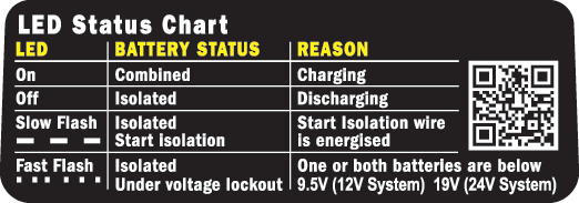 LED Status Chart Instructions Selecting Fuses and Wire Size Diagnostic Flowchart
Articles Start Lockout for Two Engines The Benefit of Serrated Flange Nuts Blue Sea Systems' Dual Circuit Battery Switch Selecting the Appropriate Fuse Rating When Installing the 120A SI ACR Battery Isolators and Automatic Charging Relays Overcoming Dropout of House Electronics during Engine Starting ACR Operation Automatic Charging Relay - An Alternative to Multiple Output Charging Systems Automatic Charging Relay (ACR) ExplainedMarketing MaterialsProduct Certificates
Start Lockout for Two Engines The Benefit of Serrated Flange Nuts Blue Sea Systems' Dual Circuit Battery Switch Selecting the Appropriate Fuse Rating When Installing the 120A SI ACR Battery Isolators and Automatic Charging Relays Overcoming Dropout of House Electronics during Engine Starting ACR Operation Automatic Charging Relay - An Alternative to Multiple Output Charging Systems Automatic Charging Relay (ACR) ExplainedProduct Certificates
Specifications
| Nominal Voltage | 12V DC 24V DC |
Start Isolation  | Yes |
| Amperage Operating Current | 175mA (combined) 15mA (open) |
| Continuous Rating | 120A |
| Intermittent Rating | 210A (5 min) |
| Cable Size to Meet Ratings | 1/0 AWG |
| Terminal Ring Diameter Clearance | 1.12in (28.45 mm) |
| Terminal Stud Length | 1.50in (38.1 mm) |
| Terminal Stud Size | 3/8-16 (M10) |
| Terminal Stud Torque | 140 in-lb (15.82 Nm) |
| Relay Contact Position | SPEC_HEADER |
| Combine 30 sec | 13.6V @ 12 V 27.2V @ 24 V |
| Combine 90 sec | 13.0V @ 12 V 26.0V @ 24 V |
| Open 10 sec | 12.35V @ 12 V 24.7V @ 24 V |
| Open 30 sec | 12.75V @ 12 V 25.5V @ 24 V |
| Open High | 16.0V @ 12 V 30.0V @ 24 V |
| Over Voltage Lockout | 16.0V @ 12V 32.0V @ 24V |
| Under Voltage Lockout | 9.5V @ 12 V 19V @ 24 V |
| Weight | 1.25lb (0.57 kg) |
Regulatory Specifications
     |
Included With
| | 7650 | Add-A-Battery Kit - 120A |
| | 8343060 | e-Series Battery Management - Merchandising Display |
| | 7650003 | Add-A-Battery Kit - 120A [Boxed] |
Frequently Asked Questions
Q: How does an ACR work?
A: An ACR senses when the voltage of either of the batteries rises to a level indicating that a charge source is active (13.0V for 2 minutes). The ACR′s contacts then connect and the ACR applies the charge to both batteries. If the voltage on both of the batteries subsequently drops to 12.75V for 30 seconds, the ACR will disconnect, isolating the batteries.
Q: How does an ACR differ from a battery isolator?
A: Battery isolators use one-way electrical check valves called diodes that allow current to flow to, but not from, the battery. ACRs use a relay combined with a circuit that senses when a charging source is being applied to either battery. ACRs are more efficient than battery isolators because they create little heat and consume minimal charging energy.
Q: Will an ACR manage the charge of my individual battery banks?
A: An ACR does not direct the charge to the battery that “needs it the most” or has the lowest terminal voltage. If there is a charge present on either battery, indicated by a high enough voltage, the ACR will combine the batteries.
Q: What Charge Sources will an ACR work with?
A: An ACR will work with all charge sources, including an alternator, AC charger, or solar panel. However, low current charge sources might not produce the voltage rise required to force the ACR to combine.
Q: Why didn't the ACR disconnect when my engine was turned off?
A: The ACR will not disconnect until the low voltage threshold is reached to isolate the circuit. It may take several minutes for the voltage of the batteries to drop to this level. Since the ACR incorporates a delay, additional time (up to 2 minutes) is required before the ACR disconnects.
Q: How many ACRs do I need?
A: To combine two battery banks, one ACR is needed; to combine three battery banks, two ACRs are required.
Q: What are the minimum number of connections I need to make my ACR work?
A: Three: One wire to each battery, and one for a ground (GND) connection. For safety reasons, remember to disconnect the negative battery connections before beginning any ACR installation. For more information read this artcile on selecting the right fuses for Blue Sea Systems ACRs.
Q: Do you have an ACR for more than two battery banks?
A: One ACR will manage the charge between two battery banks. Three battery banks will require 2 ACRs, four battery banks will need three ACRs.
Q: What does the flashing light mean on my ACR?
A: A slow flashing LED means that the start isolation wire is energized. A fast flashing LED means that one or both batteries are below 9.5V (12V System) / 19V (24V System)